
Current Digital Issue
|
|
Click to read.
|


Service Technician Training: Electricity for Servicepeople, Part 23: More on Latching Circuits
By Gary Weidner / Published April 2014

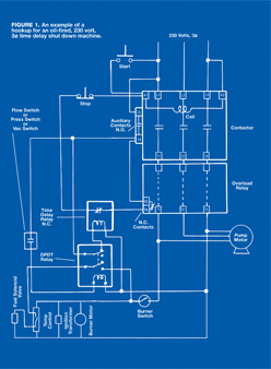
The previous chapter explained contactor latching and presented single-phase and three-phase latching circuits. This chapter details an example of how the basic latching circuit can be expanded to include additional functions.

Comparison with Basic Circuit
The circuit presented in the illustration looks somewhat complex. But, like so many things, it can be broken down into component parts. For example, as long as the contacts of the time delay relay remain closed, the upper half of the circuit is no different from the three-phase latching circuit that was discussed in the previous chapter.
Let’s briefly review the latching, using the circuit illustrated here. Assume that the machine is turned off. One side of the contactor coil (A2) is connected directly to one of the incoming power lines. The other side of the coil (A1) has two possible pathways to complete a connection to another incoming power line.
One pathway is via the normally open, momentary “start” switch. When the operator presses the “start” switch, the coil is connected to two of the incoming lines, and the contactor is energized.
The latching occurs because once the contactor is energized, the contacts between 13–14 close. This creates a pathway from A1 through the normally closed “stop” switch and the normally closed time-delay relay contacts, and the normally closed overload relay contacts (95–96) and 13–14 to the other power line.
The only difference between this latching circuit and the one presented in the previous chapter is that the contactor can be deenergized by opening either the normally closed “stop” switch or the normally closed time-delay relay, instead of just the “stop” switch.
Time-Delay Shutdown
Automatic time-delay shutdown can be accomplished by adding two components to the latching setup: a time-delay relay (“timer”) and a double pole double throw relay. The relay allows the machine’s pressure switch (or flow switch or vac switch) to be used to control both the oil burner and the time-delay function. A cold water machine doesn’t need the relay, just the timer.
The circuit works as follows. (In the illustration, the machine is turned off.) When the machine is running, voltage is available at contactor auxiliary terminal 14. If the operator is spraying, the normally open contacts of the pressure/flow/vac switch are closed. That, in turn, energizes the relay.
When the relay is energized, its contact arms switch to the opposite position from the one shown in the illustration. That leaves one side of the coil of the time-delay relay not connected to anything, so its normally closed contacts remain closed.
Now, suppose the operator stops spraying. Let’s say he puts down the spray gun and goes to lunch, forgetting to turn off the pressure washer. When spraying stops, the pressure/flow/vac switch contacts open. That, in turn, deenergizes the relay coil, so the relay contacts drop back to the position shown in the illustration. That, in turn, causes voltage to be applied to the coil of the time-delay relay. The time-delay relay operates its contacts a preset amount of time after its coil is energized, opening the latching circuit and deenergizing the contactor.
Burner Operation
Except for control of the fuel solenoid valve, the oil burner circuit is just an appendage hanging from the rest of the setup. Notice that power for the oil burner comes from the T1 and T3 terminals of the contactor/overload. That way the burner cannot get power unless the water pump is running, and a trip out of the overload relay shuts down the burner as well as the water pump motor.
Next in line is the burner switch. It has to be “on” for any part of the burner to be energized. Closing the burner switch supplies voltage to the burner motor, the ignition transformer, the temperature control, and a normally open contact of the relay. (The temperature control is assumed to an electronic-type that requires power connections just to operate.)
With the machine running and the burner switch “on,” the burner will fire whenever voltage is applied to turn on the fuel solenoid valve. Whenever the operator is spraying, the relay is energized and, if the temperature control contacts are closed (calling for heat), voltage is applied to the fuel solenoid.
Other Doodads
There are various useful embellishments that manufacturers can add to circuits like the one we discussed here. One example is an elapsed time indicator (“hour meter”). Another is a pilot light that indicates whether the machine is “on.” Either device can simply be connected to the A1 and A2 terminals of the contactor so that they operate whenever the water pump is running.
Some Notes
 The wiring details of an oil-fired, time-delay-shutdown, three-phase pressure washer can be implemented in various different ways. The circuit we discussed is just one of them. If you find yourself looking at something quite different, don’t panic. All circuits operate according to the same electrical principles, so the sooner you get familiar with those principles, the less uncomfortable you’ll be when you encounter an unfamiliar hookup.
Remember that the line-to-line voltage is the same for all three of the three-phase lines. So, instead of L1 L3, the voltage to operate the contactor coil could just as well have been taken from L1–L2 or L2–L3. Likewise, the oil burner could have been operated from any two output terminals of the contactor/overload.
In our circuit, all devices must be designed for 230 volt operation. It’s no problem to get 230 volt components, but what if the three-phase power is 460 volts? The usual answer is to connect a stepdown transformer to the incoming power lines. The step down transformer supplies power for all controls and also the oil burner.
Stepdown transformers are readily available with multiple connections so that they can be used for either a 4:1 or a 2:1 ratio (460 to 115 volts or 230 to 115 volts). The nice part about such a dual voltage transformer is that it allows all of the control components and the burner system to operate at 115 volts, regardless of whether the supply is 230 or 460 volts.
There Can Be More
Circuits of the type we discussed here can get considerably more elaborate. Remote control stations with indicator lights are not unusual. Perhaps there will be a remotely controlled solenoid valve for chemical control. The automatic shutdown may be complemented by automatic startup (unit starts if operator squeezes spray gun).
A savvy customer who knows electricity may take advantage of the control circuit to tie in various functions external to the pressure washer. One installation I’ve seen required a draft inducer fan in the stack pipe from the pressure washer. A sensor mounted in the stack was wired into the machine so that the burner could not come on unless the stack had proper draft.
Another installation in a water discharge sensitive location had a pH monitor wired into the machine’s contactor latching circuit so that the machine would shut down if a pH limit was exceeded.
Remember ¼
If you open up a machine and find a complicated maze of wires and components, it’s really a collection of simpler circuits all hooked together. And even a person well trained in electricity needs time to understand the operation of a new circuit. If you haven’t seen it before, don’t be embarrassed to announce that you’ll need some time to figure it out.
Key Concepts
• If a contactor latching circuit is used in a machine, the manufacturer can easily add a number of functions.
• Examples of add-on functions are hour meter, indicator lamp(s), remote control stations, auto-start, and customer-specific functions.
• A complicated-looking electrical system in a machine can be under- stood by breaking it down into a collection of simpler circuits.
Go Mobile