Service Technician Training: Electricity for Servicepeople, Part 19:
Pressure Washer Electrical Components (Sensors, Continued)
By Gary Weidner / Published November 2013

The previous chapter listed electric power supply and control items and began a look at sensing devices, starting with the familiar pressure, vac, and flow switches. In this chapter, we will continue to catalog the sensing components most often seen on pressure washers. Keep in mind: No matter what they look like, almost all sensing devices on pressure washers function as switches. The only difference is what type of actuator in the sensor operates the switch.
More on Flow Switches
The high pressure line flow switch described in the October 2013 issue of Cleaner Times | IWA is the style most commonly found on pressure washers. From time to time, you will encounter other styles, including some that are installed in the low pressure water line feeding the pump. In every case, a mechanical means of sensing a certain amount of water flow operates a switch.
You may have encountered what I would call a dual- operation flow switch. It is used by some manufacturers to implement an “auto start” feature on pressure washers. By auto start, I mean that the pressure washer will go from “off” to normal operation if the operator simply squeezes the trigger gun. No controls need be operated to turn on the machine.
As a concept, auto start is certainly not unusual. Many machines, especially of European design, use a high pressure switch and a contactor to turn a unit on/off with operation of the trigger gun. Others use a microswitch mounted to the unloader, plus a contactor, to shut off the machine when the unloader goes into bypass. (See the section on position sensing below for details.)
 The auto start systems just mentioned use “pressure trapping” unloaders. A weakness of these systems is that a leak, even a very small one, in the high pressure system (including the hose, couplers, and trigger gun) causes a gradual loss of pressure when the machine isn’t running. When the pressure drops to the set point of the high pressure switch, the machine comes on and runs until the pressure is pumped back up; then the pressure switch shuts the machine off again. It’s obviously undesirable for an unused unit to go on cycling like that.
Some manufacturers feel that “flow activated” unloaders are preferable to the pressure trapping type, because the flow activated unloader leaves no pressure in the high pressure discharge lines when the machine is shut off. Many also prefer feeding the pump from a float tank, rather than direct feed, especially on larger machines.
 This presents a dilemma if auto start is also desired. With no pressure in the discharge lines, and no pressure feeding the pump, how can we sense if the operator has opened the trigger gun (assuming we do not want to use electrical or electronic remote controls)? The dual operation flow switch was conceived to address this situation.
Figure 1 shows in representative form the workings of a dual operation flow switch. When the pressure washer is running and water is being sprayed from the trigger gun, high pressure water flows from the high pressure inlet, through the flow switch, to the outlet. From there the water goes to the heating coil on a hot machine, or to the trigger gun on a cold machine. Notice that the check valve in the low pressure inlet line is shut, preventing high pressure water from flowing out the low pressure inlet.
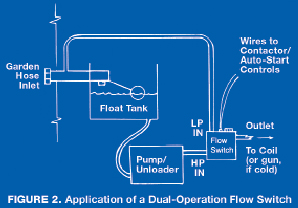
Now, suppose that the pressure washer is shut off and there is no pressure in the high pressure lines. If water at garden hose pressure is supplied to the low pressure inlet, opening the trigger gun will allow water to flow past the check valve, through the flow switch, and out of the machine. If conditions are set up right, this flow will operate the flow switch, which can then be used to turn on the machine. (See Figure 2.)
Temperature
High-Limit Switch—For the sake of safety, even the simplest hot water machines need some sort of sensing and control of temperature. This usually takes the form of the high limit or “snap” switch. The high-limit switch is a normally-closed switch operated by a bimetal sensing element. Such an element is made of two different metals joined together.
Because of the different expansion rates of the two metals, the element changes its shape as temperature changes. The movement of the bimetal element is calibrated to open the switch at a specific, preset temperature. The switch is installed in the hot water discharge line so that it will turn off the heat if the discharge water should become abnormally hot.
The high-limit switch works by the same principle as the “thermal overload” built into many single-phase electric motors. However, the high-limit switch is designed to automatically reclose its contacts when it cools, whereas the thermal switches on pressure washer motors are designed to remain deformed in the open position until a reset button is pressed to reclose them.
Because each high-limit switch is calibrated to open at a particular temperature, care must be taken when replacing one to use a new switch of the same temperature rating as the original. You may encounter the fusible link type of high-limit switch, especially on the coil inlet line of some European machines. In this switch, contact is maintained by a special link that is calibrated to melt and open the circuit at a particular temperature.
And here’s a cautionary note: the high-limit switch can only sense the water temperature in the portion of the discharge line where it is installed. Consider this scenario: a flow or pressure switch fails, causing the burner to continue firing after the trigger gun is shut off. The water temperature in the heating coil rapidly rises unacceptably high, but the high-limit switch doesn’t shut off the burner. Why? Because the overheated water is not flowing out of the heating coil and past the high-limit switch. (Remember, the trigger gun is shut off.) Throw in a clogged pressure relief valve, and you’ve got the makings of a steam explosion.
Bimetal Thermostat—The next level of sophistication beyond the high-limit switch is the thermostat. The simplest type of thermostat works much like the high-limit switch. The difference is that a screw adjustment is provided to control the movement of the bimetal element when temperature changes. The result is a switch that can be set to operate at various different temperatures, depending upon where the adjustment screw is set. (The adjustment screw is usually fitted with a knob for easy adjustment.) If the thermostat has been calibrated, it will include dial markings for various temperatures over the range that it can function. However, this type of thermostat is usually made very inexpensively, and its dial markings are likely to be just “cold, warm, hot.”
Hydraulic Thermostat—The hydraulic type of thermostat is a little more sophisticated than the bimetal thermostat. It’s more accurate, usually calibrated in degrees. It’s also more versatile in mounting. The bimetal thermostat must be mounted right where it has to sense temperature. The hydraulic thermostat is usually designed to mount on a control panel and has a remote sensor that is installed in the discharge water line.
The sensing portion of a hydraulic thermostat is a cylindrical metal bulb that contains a special liquid, which expands or contracts considerably with temperature changes. This is just like the sensing bulb at the bottom end of a glass thermometer. The bulb is connected to the main body of the thermostat by a length of very small diameter tubing, called a capillary tube. This tube is so small that it is often mistaken for an electric wire, especially if it has a protective plastic sleeve that resembles wire insulation.
Inside the main body of the hydraulic thermostat, the capillary tube feeds its liquid to one side of a diaphragm. An increase in temperature causes the liquid in the sensing bulb to expand, travel up the capillary tube, and move the diaphragm. Movement of the diaphragm operates an electric switch. As with the bimetal thermostat, an adjusting screw is provided to control the amount of diaphragm movement needed to operate the switch. Put a knob on the screw and calibrate the front dial in degrees, and you’ve got a nice thermostat.
RTD Thermostat—The RTD thermostat is the most sophisticated type found on pressure washers. Compared with the bimetal or hydraulic types, it is faster responding, more accurate, and can be set up to hold a temperature very close to the desired setting.
The letters “RTD” stand for “resistance-temperature device.” The operation of this thermostat is based on the fact that the resistance of many types of resistors varies with temperature. The complete device consists of a temperature sensing resistor, connecting wires, and an electronic module containing a circuit board. The electronic circuitry in the module monitors the resistance of the sensing resistor, which is encapsulated in a probe that is installed in the hot water discharge line. There is a specific relationship between the resistance of the probe and the temperature to which it is exposed.
The front of the module has a temperature adjustment knob that works like the volume control knob on a radio. When the water temperature causes the probe resistance to reach a value determined by the knob setting, a relay in the module operates a set of contacts. RTD thermostat modules require power to operate, be it 24, 120, or 240 volts. RTD thermostats can be rugged and reliable, except if the module gets wet!
A service note: there are different kinds of resistance probes used with different RTD modules. Taking a resistance measurement of the probe won’t tell you much unless you know what the resistance should be at a given probe temperature. Some RTDs use positive temperature coefficient probes, where the resistance of the probe increases with increasing temperature. Other RTDs use negative temperature coefficient probes, called thermistors, where the resistance of the probe decreases with increasing temperature.
Level
Pressure, flow, and temperature are the most important liquid properties to monitor in a pressure washer. But another liquid property, level, is sometimes of concern. Two types of liquid level sensors can be found on pressure washers.
Float Level Sensor—In this type of level sensor, a buoyant float operates a switch whenever the float rises or falls to a certain level in a tank or container. In one version, the float is mounted to the end of a pivoting arm, just like on a float valve. But instead of operating a float valve, the float and arm operate a switch. This version can be found in some gasoline engine crankcases, where it is used to sense a low oil level.
Another version works much like the flow switch discussed earlier. In this device, a doughnut-shaped float contains a magnet. The float rides up and down along a hollow rod that contains a reed switch located at the level desired to be sensed. This configuration is sometimes used to sense a low fuel level in a burner fuel tank.
Electrical Level Sensor—The electrical level sensor, like the RTD thermostat, consists of a sensing element, connecting wires, and an electronic module. The sensing element is nothing more than two electrodes mounted in the liquid container at the level to be sensed. This type of sensor only works with a liquid that will conduct electricity.
If the sensing electrodes are immersed in the liquid, the electronic module “sees” electrical continuity between the electrodes. If the liquid level falls below the electrodes, leaving air between them, the electronic module “sees” the electrical open circuit. This type of sensor can be used in a container for liquid scale inhibitor, because the inhibitor is electrically conductive.
Position
Occasionally, the position of an object needs to be sensed by a switch. An example is a “door switch” that senses whether a door or enclosure is properly closed. This is just like the home washer and dryer application, where these machines will not run unless the door or lid is closed.
Another example is the switch mounted to the unloader in some auto start/stop pressure washers. Unloaders have a central spindle that moves along its axis as the unloader changes between spray and bypass modes. It’s common for one end of this spindle to project out of the unloader body. If a microswitch (a very compact type of switch) is positioned at the end of the unloader spindle, it can sense whether the unloader is in the spray or bypass mode.
Some suppliers of unloaders offer versions with the microswitch already in place as part of the unloader. In addition to auto start/stop applications, these unloaders are widely used to operate burners in conjunction with the trigger gun.
Flame Sensors
Several different devices are used to verify whether a gas or oil flame is lit. A gas burner may employ a thermocouple or an electronic sensor or a mercury probe to verify that a pilot flame is present. An oil burner may be equipped with a primary control that uses a CAD cell to verify that the burner is lit. (“CAD” means a cadmium sulfide or cadmium selenide electric eye.) Most of these devices were discussed in the Service Department articles on oil and gas heat.
Key Concepts
• No matter what they look like, almost all sensing devices on pressure washers function as switches.
• Temperature is sensed by means of its effects on materials, such as by expansion or contraction of metals or liquids, or by changes of electrical resistance.
• A dual (high pressure/low pressure) operation flow switch can be used to implement auto-start.


