Current Digital Issue
|
|
Click to read.
|

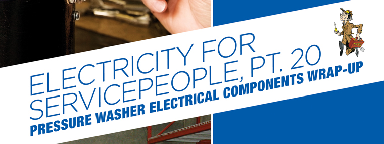
Service Technician Training: Electricity for Servicepeople, Part 20:
Pressure Washer Electrical Components Wrap-Up
By Gary Weidner / Published December 2013
This third chapter on electrical components will complete the listing and brief descriptions of devices that may be found on pressure washers. The 20 chapters so far on electricity provide a foundation of knowledge needed to go into electric circuits and troubleshooting.

Indicators
An indicator is a device that provides the operator or service technician with information. The information may be a simple “yes-or-no,” as provided by the “idiot” lights on some car dashboards. Or, the information may be a measured value of some parameter, as provided by the gauges on some car dashboards. Following are descriptions of some indicator devices.
• Lights—A light bulb is a classic example of a status indicator. It can be used to show whether electric power is being supplied to a machine, whether the machine is turned on, whether the heating system is turned on, whether a chemical solenoid is activated, or to indicate problems or malfunctions.
Nowadays, the role of the light bulb is played by any of three different devices, but the results are all the same: they light up when supplied with a voltage. Miniature, incandescent bulbs were the first to be used, and are still often employed. One of their attractions is that they come in a wide range of operating voltages.
Neon lamps have replaced incandescent bulbs in many applications. Neons take a very long time to burn out, and they’re cheap and rugged. Applications are normally limited to 115, 230, or 460 volts.
The third type of device is the LED (light emitting diode). These rugged, solid-state devices require low voltage dc for their operation. The most commonly available color is red, and there are lots of them to be found. Perhaps your coffee maker has a little red power indicator next to the timer, or maybe your car has a center, high-mounted brake light that consists of a row of little red dots. Those are LEDs. Each LED produces only a pinpoint of light, so they have to be grouped for a lot of applications, such as a cluster of them for a tail light. Because of the low voltage dc requirement, LEDs are most likely to be found on pressure washers that have some sort of electronic circuit board in them.
• Elapsed time indicators—That’s the proper terminology for hour meters. Some are electronic, but many are still the traditional electromechanical type. Hour meters are readily available to run on 12 Vdc and 24, 115, or 230 Vac.
• Readouts—A readout is an electronic display of information. Two types are seen frequently: LED and LCD. The LED readout contains illuminated characters, usually red. The characters are actually LEDs arranged in the desired shape. The LCD (liquid crystal display) is not self-illuminating. It consists of a gray panel, on which black characters appear. Both the LED and LCD readouts require circuit boards to drive them. These readouts are used to display things like temperature, elapsed time, and rpm.
Protective Devices
Protective devices are intended to protect the equipment, the operator, or both from the effects of misuse, abuse, or malfunction.
• GFCI — The GFCI (ground fault circuit interrupter), also referred to as a GFI, protects the operator against one of two types of electrocution. It prevents a lethal current from flowing through the operator to ground. It does NOT protect against current flowing through the operator and back into the electrical system! That’s important to know, because it is possible to be quite thoroughly electrocuted without tripping a GFCI!
• Fuse—A fuse is an overcurrent protection device. If a fuse blew, more than the intended amount of current was flowing through the wire(s) fed by the fuse. You’ve got to correct the problem that caused the fuse to blow, or you’ll just blow more fuses. It’s important to replace a blown fuse with the correct fuse. Fuses have voltage ratings and current ratings, and some are designed to blow very quickly while others are designed to tolerate temporary overloads without blowing. A simple blown fuse isn’t always quickly spotted, partly because a fuse on a piece of equipment isn’t always obvious. Some fuses are mounted through the control panel. Some are the in-line type. Some are contained within terminal blocks.
• Circuit breaker—A circuit breaker is in essence a reusable fuse. It trips if too much current flows through it, and then it can be reset (sometimes after a cool-down period).
• Overload relay—An overload relay is a device used with and mounted to the output side of a contactor. It functions much like a circuit breaker, except in the way that it opens an overloaded circuit. Current flows through the overload relay to the load. If the current becomes excessive, the overload relay opens the circuit that operates the contactor, causing the contactor to open.
• Surge suppressor—A surge suppressor is an electronic device that is connected across the wires feeding a component. Under normal operating conditions, it does nothing and is, in effect, not there. However, if a “spike” of abnormally high voltage appears across the wires, the surge suppressor absorbs the excess voltage and prevents the spike from traveling into the component. Surge suppressors are also frequently used in the reverse sense of the fore- going. That is, a component that tends to produce voltage spikes (such as a coil) may have a surge suppressor hooked across it to prevent the spikes it produces from damaging it or other components.
Fluid Control
• Solenoid valve—The only electrical component used for fluid control in pressure washers is the versatile solenoid valve. The valves are often manufactured with interchangeable electric coils, so that the same valve can be configured to operate from various dc and ac voltages. Solenoid valves allow fluid flow to be turned on or off by remote control. They are used to control fuel flow to oil and gas burners, chemical intake to water systems, metering of liquid water conditioner (anti-scaler), and occasionally in auto-cooldown systems.
Miscellaneous Control Components
• Relay—A relay is a switch that is operated by a solenoid coil. Relays were discussed in Chapter 47 (CT|IWA, November 2012).
• Timer—Also known as a time delay relay. This device is a relay that also contains an electronic timing circuit. When a signal is sent to operate the relay, the timing circuit delays operation of the relay for a specified amount of time. On some, the amount of time delay is adjustable; on others it is fixed.
Some timers are entirely solid-state, while others combine an electronic timer with an electro- mechanical relay. Timers take a variety of shapes. Some are rail mounted; some are pin-type plugin units; some are cube-shaped.
• Control transformer—This is a small, low-power transformer used to supply a control circuit voltage that is lower than the power line voltage. Power line voltages are usually 115, 230, or 460 volts. Control circuit voltages are usually 24 or 115 volts. Household examples of similar devices are doorbell transformers and the transformers used to provide low voltage for heating and air conditioning controls.
• Stepdown transformer—This is a larger, more powerful version of the control transformer. A stepdown transformer may be used, for example, to operate a 115 volt oil burner on a machine that uses a 230 volt pump motor. Note: transformers are rated in voltamperes. See Chapter 46 (CT|IWA, October 2012) for a discussion of transformers.
• Burner control module—More and more pressure washer manufacturers are using electronic ignition control modules on gas-fired machines. By the way, these modules usually require an operating voltage of 24 volts. Ignition controls were covered in Chapter 30 (CT|IWA, May 2011). There is an oil burner counterpart to the gas ignition control module. It’s called an oil primary control and it’s been around for ages, but is not often used on pressure washers. The primary control checks for combustion flame, and shuts down the burner or the fuel supply if it sees no flame. Modern primary controls can also provide pre- and post-purge cycles, similar to the gas control modules.
• Touchpad—A touchpad is a miniature keyboard with just a few “keys” on it. It’s an array of switches, often the so-called membrane type. Usually, the “keys” of the touchpad are connected to a circuit board, which converts key touches into control signals for the machine. This device should not be confused with the touch screens found on many computers and smart phones.
That completes the listing of electrical components you are most likely to find on pressure washers. In the next chapter, we’ll look at how the components are connected together to form electrical circuits.
Key Concepts
• An indicator is a device that provides the operator or service technician with information.
• The information may be a simple yes-no, or it may be a measured value of some parameter.
• The classic yes-no indicator is a light bulb.
Go Mobile