Current Digital Issue
|
|
Click to read.
|

Past Digital Issues
|
|
Click to read.
|


Service Tech Training: Principles of Pressure Washer Design, Part III
By Gary Weidner / Published July 2016
Editor’s Note: This service technician training series was published previously from September 2008 through June 2014 in Cleaner Times|IWA. It is being republished with the recognition this material is not exhaustive of the subject at hand, but rather to present to new servicepeople an all-important fundamental understanding of how things work. Part I of Principles of Pressure Washer Design was republished in the March 2016 issue and Part II in the May 2016 issue of Cleaner Times.
Let’s continue to tinker with the crude pressure washer we put together over the past two months. Recall that first we put it together with just a wand, no trigger gun. In order to add a trigger gun, we used a pressure switch to stop the pump whenever the gun was shut off.
Divert The Flow
Remember that it was mentioned that there’s another way to put together a trigger gun setup. When the gun is off, instead of stopping the pump, we can divert the flow coming out of the pump.
The Unloader
You may already be aware that the flow is usually diverted by means of an “unloader” valve. The unloader valve comes in a variety of flavors, but right now let’s just look at how it would function in our washer.
When our pump is running and our gun is spraying, the unloader valve automatically sets itself to position #1 in Figure 1. If the gun is shut off, the valve senses the rising pressure or the stopped flow or both and automatically sets itself to position #2.
Now the water flowing out of the pump is diverted back to the pump inlet. This is often referred to as the bypass mode. If the gun is squeezed again, the unloader valve senses the opening of the gun and automatically sets itself back to position #1.
Like almost any device, an unloader valve can malfunction, so we still need the overpressure relief valve.
A washer can be designed to use both of the trigger gun methods we have discussed. For example, some machines are constructed with an unloader valve that also has an electric switch attached to an external moving part of the unloader. In this design, whenever the unloader switches into the bypass mode, the pump is shut off.
Pros and Cons
A benefit of the unloader approach is that we avoid the strains of constant stopping and starting. Then too, when the user is finished washing, the running pump and motor may serve as a reminder to turn off the machine.
The possibility that a pressure switch may leak is not overcome by using an unloader because the unloader, too, can leak and malfunction.
Probably the biggest drawback to the unloader approach is that most high pressure pumps cannot tolerate operation in the “bypass” mode for more than a few minutes without accelerated wear. Since it’s not unusual for poorly trained users to leave the machine running in bypass mode while they take a coffee break or even a lunch break, problems can arise because the temperature of the water circulating in the bypass loop rises rather rapidly.
This situation can be overcome at the expense of adding more components to the design. Many pressure washer manufacturers install a temperature-operated valve to dump heated water. The valve is often referred to as a “pump saver valve.” (Some premium pumps are capable of withstanding hot water in the bypass loop.)
Bottom Line
How does the use of an unloader to allow for a trigger gun stack up against stopping the pump? My comments are the same as last month: depends on who you ask. It’s a proven method, and I think its performance and reliability are fine, provided the manufacturer uses a good design and high quality components.
The Float Tank
Another refinement we will make to our washer is the addition of a “float tank” as sketched in Figure 2. This is useful for both the stop-the-pump and divert-the-flow designs. It’s commonly called a float tank because it contains a float-operated valve, like a toilet tank. There are several benefits to feeding the incoming water into a reservoir:
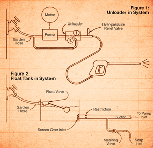 Buffering. In the direct hookup of Figure 1, we’re at the mercy of any glitches in the incoming water supply.
The space between the float valve discharge and the surface of the water can provide backflow prevention for the water spigot.
Greater versatility. For example, since the pump now draws from an unvarying water source, we can slightly restrict the water flow from the tank to the pump as shown in Figure 2 so that there will be suction in the pump intake line. That suction allows us to tap into the pump’s water intake line and feed in soap as desired through a soap intake line with a metering valve.
Notice that we have also put a screen on the inlet of the pump suction line (in the float tank) to help protect against whatever may fall into the float tank.
Service Tip: Coping with Tangled Wires
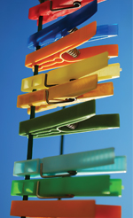
Problem: Some pressure washers have quite a few wires in their electrical control panels. The pressure washer manufacturers neatly bundle the wires so everything looks nice. That is, until you have to cut open the bundles to trace wires and do repairs. Then you find yourself confronted with a rat’s nest of wires.
Solution: Keep a few spring-type plastic clothespins in your toolbox, and use them to temporarily clip wires in place or out of the way while you’re working. Wooden clothespins work too, but I like the plastic ones because they come in assorted colors, which are sometimes a help in keeping wires sorted, and they don’t absorb moisture.
Go Mobile