Current Digital Issue
|
|
Click to read.
|

Past Digital Issues
|
|
Click to read.
|


Service Technician Training: Electricity for Servicepeople, Part 24: Troubleshooting
By Gary Weidner / Published May 2014
The preceding two chapters covered “contactor latching” and some typical related circuits. In this chapter, we’ll take a look at troubleshooting malfunctions in these circuits.

Effects of Malfunctions
When you go to troubleshoot a piece of equipment, you are like a doctor, and the equipment, the patient. How does the doctor diagnose what’s wrong? There’s only one way: determine the patient’s symptoms and analyze them. The symptoms may be readily observable, such as shortness of breath or dizziness, or they may be subtle, requiring sophisticated devices to detect them.
So it is with equipment: all malfunctions result in some sort of symptoms. Analyzing those symptoms is what troubleshooting is all about. It is important that you understand a circuit that you are troubleshooting so that you can look for and interpret the symptoms. By the way, the doctor often finds that the patient’s set of symptoms could be produced by any of several causes. That happens in equipment troubleshooting too—one more reason to learn how the circuit is supposed to function.
Diagnosing the Circuit
Our “patient” will be the time delay shutdown circuit from the previous chapter. For convenience, it’s reproduced here. The table shown presents a list of circuit components with the symptoms that would result from failure of each of the components. The first thing to notice is that it’s common for a component to have at least two different ways to fail: “shorted” or “open.” An exception is a vac switch. While a flow or pressure switch can fail “short” or “open,” a vac switch seldom fails “short.”
Note: it’s assumed here that if you’re checking this circuit because the equipment just plain won’t run, you’ve already checked out the incoming power. (What do the medical folks commonly do first thing when you go to them because something’s wrong? They automatically check some basic things like pulse, blood pressure, respiration rate.) On three-phase systems, all three lines must have proper voltage! “Two outa three ain’t bad” doesn’t apply when you’re talking power lines.
When a three-phase machine won’t run, the first thing to check is the first item in the table: the overload relay. If the overload is tripped, reset it and run the machine to see if you can find the reason for the trip. Perhaps the pump motor is overloaded, or maybe the three-phase voltages aren’t equal. Check the three line-to-line voltages. Use your clamp-on ammeter on each of the three power lines: are the three currents equal and not excessive? Has someone tampered with the trip current adjustment on the overload?
The table is arranged as a list of components and failure modes, but in the field, the symptoms are what you will be dealing with. Notice, for example, that the symptom “no time delay shutdown” can be caused by any of three different failures: by timer contacts stuck shut, or by flow/pressure switch contacts stuck shut, or by relay contacts stuck in the energized position.
How to tell which is the culprit? The first one, timer contacts stuck shut, is the easiest to verify. If you look at the table and study the way each component functions in the circuit, you’ll see that timer contacts stuck shut is the only type of failure that results in “no time delay shutdown,” but all other functions of the machine (start, stop, and heat) are working normally.
Suppose the flow/pressure switch contacts are stuck shut. That produces exactly the same performance symptoms as having the relay fail with its contacts in the energized position, so we have to look a little deeper. We have to look for electrical symptoms.
Key Concepts
• All malfunctions result in some sort of symptoms.
• Some symptoms of a malfunction are readily observable; others can only be detected by an appropriate test device.
• A symptom can have more than one possible cause.
According to the circuit diagram, one side of the relay coil is connected to T3. The other side of the coil gets voltage whenever the flow/pressure switch closes. Now is the time to get out that nice little neon test light.
Hold one lead of the test light to the T3 terminal of the relay coil. Hold the other lead of the test light to the flow/pressure switch terminal of the relay coil. If the flow/pressure switch is working okay, the test light will go on and off as the spray gun is triggered. If the flow/pressure switch is stuck shut, the light will stay on whether the gun is triggered or not.
What about a “no heat” situation (assuming the burner itself is not at fault)? The first thing to check is whether power is going through the burner switch. If so, the burner motor and transformer/igniter should come on when the burner switch is turned on. If they operate, then the fuel solenoid must not be getting power (again, assuming the solenoid itself hasn’t failed).
If you touch one lead of the test light to the T3 line and the other lead to the terminal of the relay that feeds the temperature control, the light will tell you if power is going to the temperature control when the spray gun is on. If so, the temperature control must be open. To verify, move the test light lead from the relay terminal to the terminal of the temperature control that feeds the fuel solenoid. The light should show no power there. (If the light comes on, then the fuel solenoid is not operating.)
A Circuit Variation
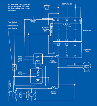 The preceding paragraphs gave a sampling of how to troubleshoot a circuit like the one illustrated. Odds are that no circuit you see will be precisely like it. Here’s a small variation that would actually be an improvement on the circuit. Look at the “start” switch. Suppose the right terminal is connected to L1 as shown. But suppose the left terminal is connected to the contactor auxiliary terminal 14 instead of to A1.
How would that change the operation of the circuit? Under normal conditions, everything would work just the same. But if the overload relay trips (its normally closed contacts open), pressing the “start” button would have no effect. That’s preferable to the hookup in the illustration, where, when the overload is tripped, the machine will run as long as the start button is held. If you can verify that from the diagram, you’re making good progress!
Component Failure Symptoms
Condition
- Overload relay tripped
- Timer contacts stuck open
- Timer contacts stuck shut
- Flow/pressure switch contacts stuck open
- Flow/pressure switch contacts stuck shut
- Relay contacts stuck in deenergized position
- Relay contacts stuck in energized position
Symptoms
- Push START button, unit starts; release button, unit stops
- Same as #1
- No time-delay shutdown
- No heat, and unit times out while spraying
- Burner doesn’t shut off with trigger gun, and no time-delay shutdown
- No heat, and unit times out while spraying
- Burner doesn’t shut off with trigger gun, and no time-delay shutdown
Go Mobile