Current Digital Issue
|
|
Click to read.
|

Past Digital Issues
|
|
Click to read.
|


Service Technician Training: Electricity for Servicepeople, Part 21: Electric Circuits
By Gary Weidner / Published February 2014

The researches of many commentators have already thrown much darkness on this subject, and it is probable that, if they continue, we shall soon know nothing at all about it.
—Mark Twain

There is no shortage of good textbooks covering electric circuits. However, the “80/20 rule” prevails; probably about 80 percent of the knowledge in these books (or videos/downloads) is of no use in servicing pressure washers. It only serves to hide the valuable 20 percent and discourage the reader with a flood of complicated information.
Having covered the necessary fundamentals of electricity and components in the preceding chapters, we’re now going to tackle electric circuits as related to pressure washers. So fasten your seatbelt, put on your crash helmet, and get ready to roll.
Analogies
Analogies can be a great help in dealing with electrical concepts. I have two all time favorites. One is that voltage in an electrical system can be likened to pressure in a water system. A voltage can be present whether or not any current is flowing, just as a pressure can be present whether or not any water is flowing.
The other is that current flow in an electrical system can be likened to water flow in a water system. There are many similarities between current flowing through a wire and water flowing through a hose.
The Electric Circuit
The first item of business is to define the term “electric circuit.” Let’s start with just the word “circuit.” Its common meanings have the connotation of going around something. In early America, the circuit rider was a clergyman who traveled around to preach at various churches. A circuit court judge is one who travels around to hold court in various locations. A race car team may compete in a racing circuit by traveling around to various tracks.
Similarly, an electric circuit is a path around which electric current can flow. There are three requirements to complete an electric circuit:
• A source of electrical energy, such as power lines or a battery.
• An electrical load, such as a light bulb or a motor.
• Unbroken connections for electric current to flow from the source to/through the load and then back to the source.
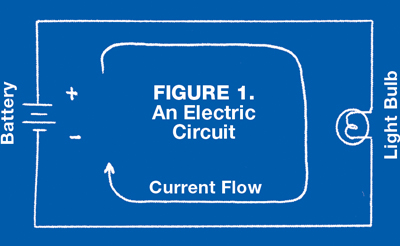 Figure 1 shows a battery powering a light bulb in an electric circuit. Notice that all three required elements are present: a source, a load, and a complete path for the current to flow from the source to/through the load and back to the source. Note: In the symbol for a battery, the end with the longer line represents the positive terminal, and the end with the shorter line represents the negative terminal.
You may have noticed an important difference between current flow and water flow. It’s no problem to let water flow out the end of a hose, say onto the ground or into a bucket. You can’t do that with electric current! No current can flow unless it can travel from a source to a load and back to the source. That’s why birds can sit up there unharmed on a bare electric wire: there is no path for current to flow through them.
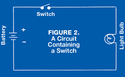 Switches are the most commonly found circuit component. In Figure 2, a switch has been added to the circuit of Figure 1. When the switch is open, it interrupts the path of the electric current.
In Figure 3, a fuse has been added to the circuit. A fuse can be thought of as a form of switch. If too much current flows through the fuse, it melts and opens the current path, just like an open switch.
Series Circuits
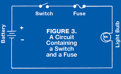 Electric circuits can be series circuits or parallel circuits or any combination of the two types. In a series circuit, all components are connected end-to-end. In the circuit of Figure 3, the switch, the fuse, and the light bulb are said to be connected in series.
Figure 4 presents a series circuit commonly found in pressure washers. The burner switch, the pressure switch (it could also be a flow switch or a vac switch), the thermostat, and the fuel solenoid valve are all connected in series.
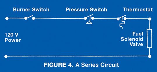 Remember that as the electric current flows through each of the series components in succession, none of the current can squirt off into the air or leak out and drip on the ground like a water leak. This leads us to an important law for series circuits: In a series circuit, exactly the same current must flow through each component. (Where else can it go?) You may measure different voltages across each component, but the current through each must be exactly the same.
Parallel Circuits
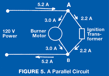 A parallel circuit is one that has more than one path for current to flow. The burner motor and transformer in Figure 5 are connected in parallel. At point “A,” the 5.2 amp incoming current divides into a 3.0 amp current to the motor and a 2.2 amp current to the transformer. At point “B,” the two currents recombine into a 5.2 amp return current. Since the ends of the components are connected together, in a parallel circuit, exactly the same voltage appears across each component. Different currents may flow through each component, but the voltage across all components connected in parallel must be the same.
Series-Parallel Circuits
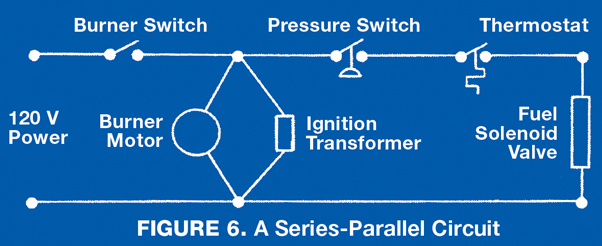 Series and parallel circuits can be connected together in any number of ways. You may have recognized the series circuit of Figure 4 and the parallel circuit of Figure 5 as parts of the wiring of a typical oil fired pressure washer. In Figure 6, the circuits of Figures 4 and 5 have been combined as they would be in a pressure washer. This is an example of a series-parallel circuit. The next chapter will continue our discussion of electric circuits.
Go Mobile